Securitron Mag Lock Wiring Diagram
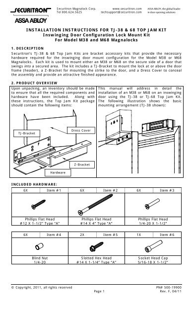
Tj 38 68 Installation Instructions Securitron Magnalock Corporation
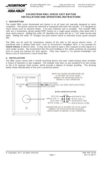
Pb4l Installation Instructions Securitron Magnalock Corporation

Securitron Keypad Diagram For Dc Lock And Dc Power Wiring
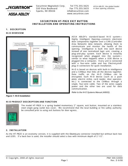
Securitron Ht Pb2e Push Button Instructions Access Control
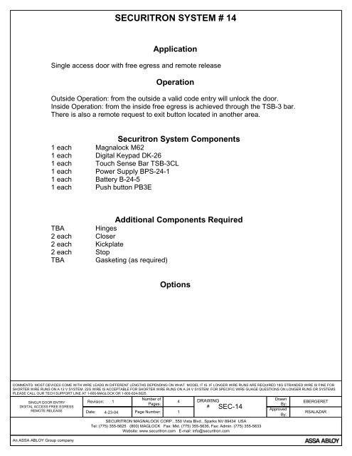
Single Door Dk 26 Remote Release Wiring Diagram Securitron

Securitron Keypad Diagram For Ac Lock And Ac Power Wiring

Alarm controls lock n a box kit lnb 6 with kp 100 keypad.
Securitron mag lock wiring diagram.
Securing Double Doors With Securitron M68ls Maglocks Locksmith Ledger

M38 68 Installation Instructions Securitron Magnalock Corporation

Securitron M32fd Face Drilled Door Position Switch Dps 600 Lb Magnalock Taylor Security Lock
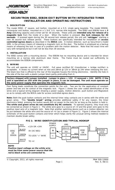
Securitron Eeb2 Eeb3n Exit Button With Securitron Magnalock

Securitron Sam Samb Sambd Samd Shear Aligning Magnalock Taylor Security Lock

Two Door Entry With Day Timer Wiring Diagram Securitron

Electromagnetic Mini Shear Lock Securitron Magnalock Corporation
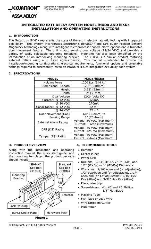
Integrated Exit Delay System Model Imxda And Iexda
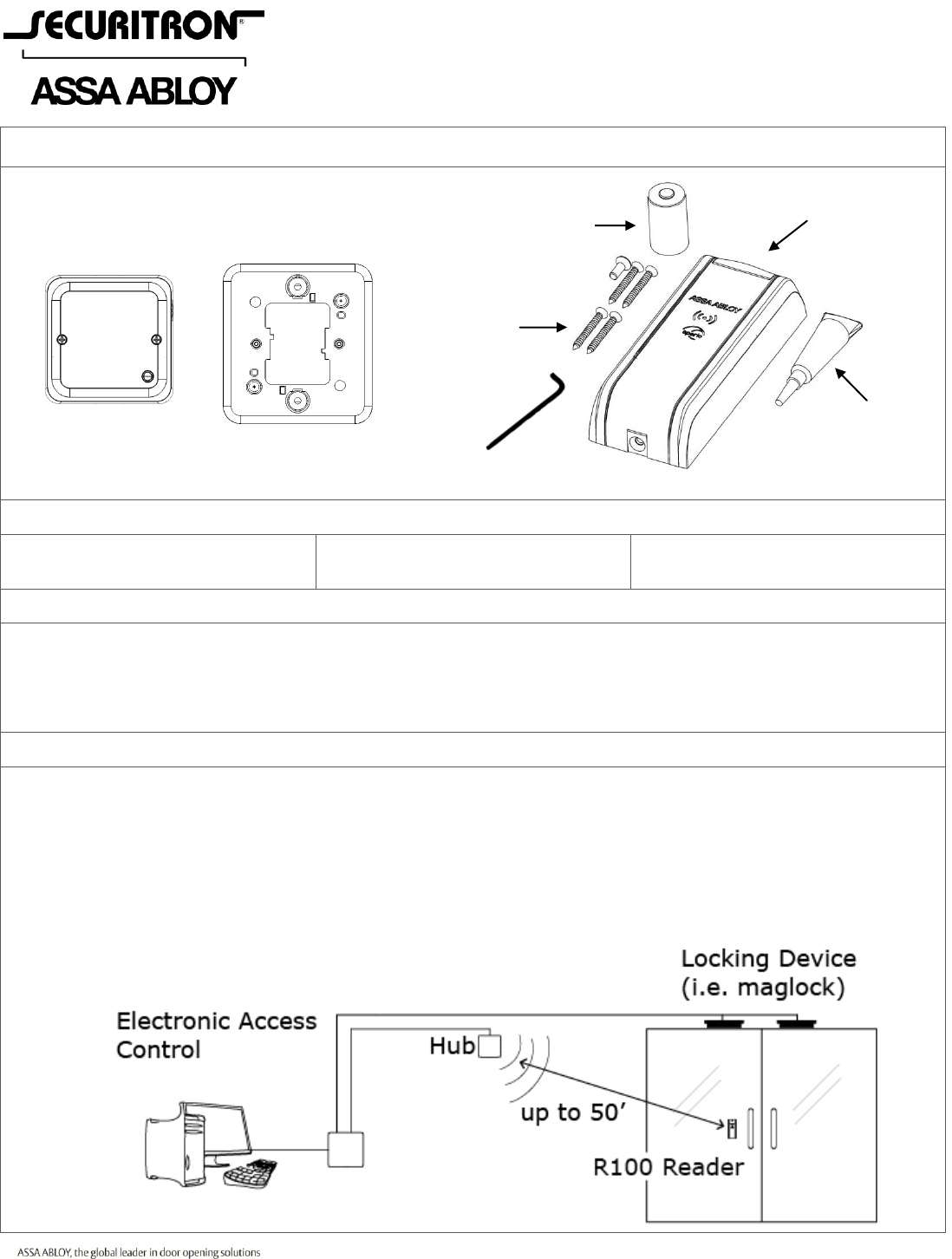
Securitron R100h Installation Instructions R100 1h I 500 24050 20a
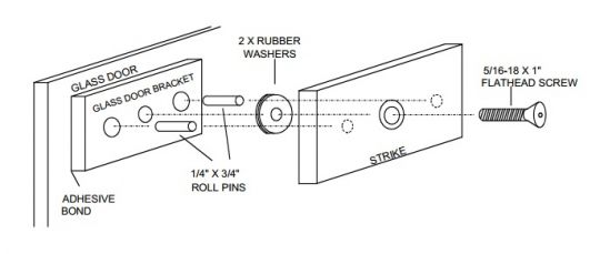
Securitron Gdb Glass Door Bracket M32 M38 M62 M68 Maglocks

Securitron M680e Ecomag Magnalock Assa Abloy

Securitron M62f M62 Magnalock 12 24 Vdc Face Drilled Hardwarelocker Com

M680ebdx 628 Securitron Maglock With Bondstat Dps And Rex In Satin Aluminum Finish Lock Depot Inc

Securitron M32 F Face Mount Magnalock For Inswing Door With Z Bracket

Securitron M62 M62b M62bd M62d M62f M62fb M62fbd M62fd M62fg M62fgb M62fgbd M62fgd M62g M62gb M62gbd M62gd Durable Magnalock Taylor Security Lock

Securitron M82fgb Series 1800 Lbs Holding Force Magnalock Electromagnetic Lock Brushed Stainless Steel Hardware Accessories
Securitron Dsb Installation And Operation Instructions Io 500 22700 20f
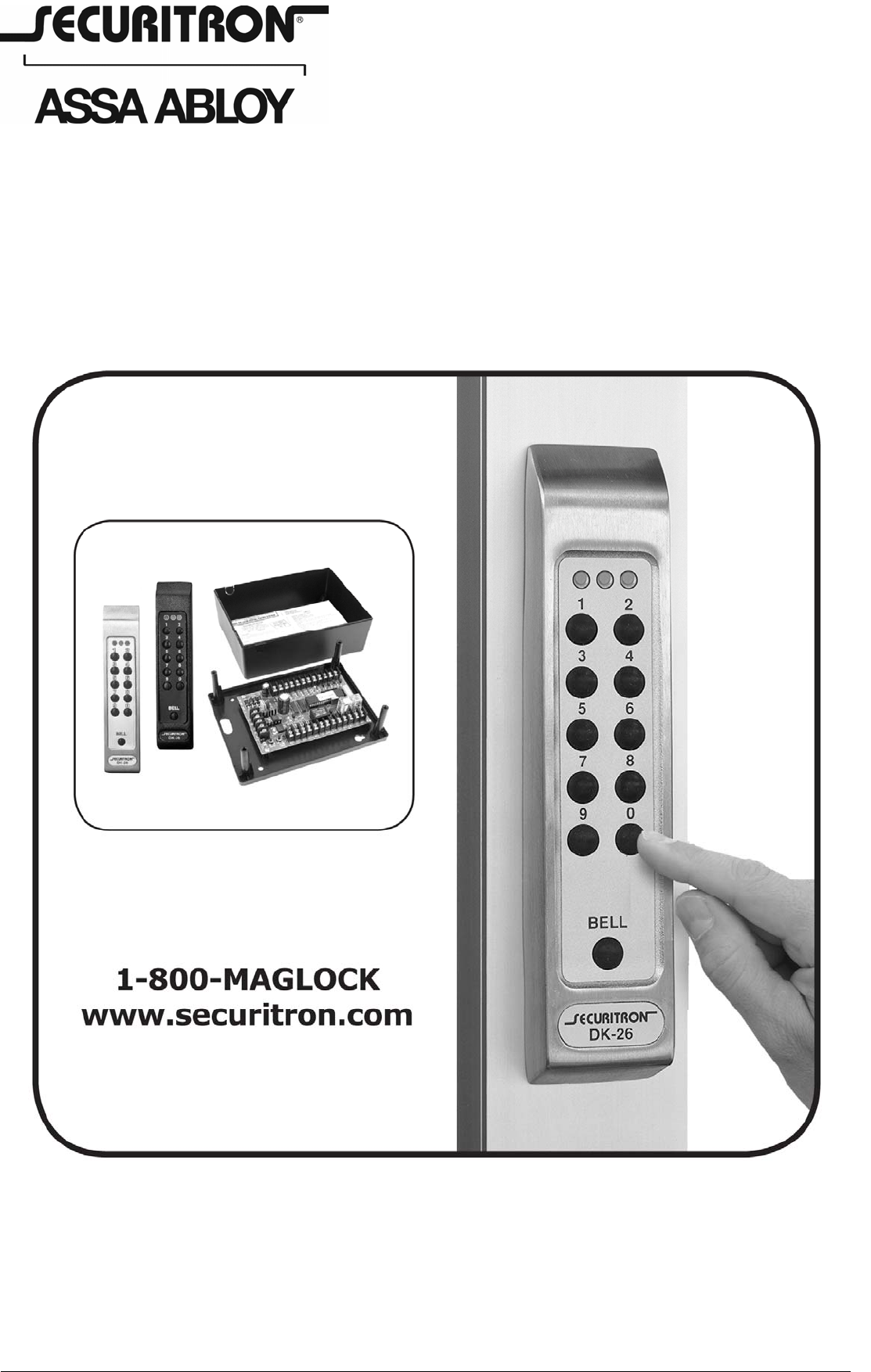
Securitron Dk26 500 16900 D Dk 26 Installation And Operating Instructions Io 16900 20d
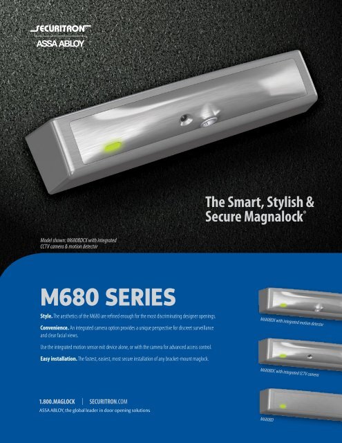
M680 Series Securitron Magnalock Corporation

Securitron Ms Maglock
Securitron Mm15 Mm15dt Mm15g Mm15gdt Specialty Locks Electromechanical Maglock Taylor Security Lock

Securitron M62fgbd Magnalock Face Drilled Gate Conduit Magnetic Bond Sensor Mbs Door Position Switch Dps 1200

Securitron M32f M32 Magnalock 12 24 Vdc Face Drilled Thebuilderssupply Com

Securitron Product Catalogue Manualzz
Source : pinterest.com
